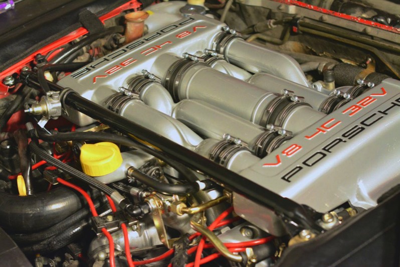
1986.5 928S Intake Refresh Procedure

In August 2013, after diagnosing a host of problems (including a vacuum leak) I decided to refresh the intake manifold of my 1986.5 Porsche 928S. It grew into a complicated job. Luckily, I had the support of the Rennlist community, and Mike Frye’s intake refresh guide, which helped tremendously. I am very grateful to both. I cannot recommend Mike’s guide highly enough to those undertaking this procedure for the first time.

NEW PARTS

O-Ring (between Air Guide and Throttle Body) 999 701 436 40 Sealing Ring (between Air Guide and MAF) 999 701 699 40 Sealing Ring (between Air Guide and MAF) 999 701 183 50 Connecting hose (to Heater Valve) 928 574 567 03 Check Valve (to Brake Booster) 928 355 660 03 Gasket (between the water bridge and the engine block) 999 701 627 40 Gasket (inside the water bridge and mates with the thermostat) 928 106 163 00 Gasket (fits between the thermostat and the elbow, called cover for regulator housing in PET) 999 701 632 40 Gasket (for water bridge) 928 106 227 00 Gasket (paper, for water bridge, in addition to 928 106 227 00) 928 106 167 01 Gasket (Oil Filler Neck) 928 107 707 04 2 Gaskets (Intake Manifold) 928 110 566 04 2 Gaskets (Valve Covers) 928 104 447 06 8 Gaskets (Spark Plugs) 928 104 443 08 Hose (to Oil Filler Neck) 928 107 445 00 Hose (Idle Stabilizer Valve to Air Guide) 928 110 442 05 Hose (Idle Stabilizer Valve to Center “T”) 928 110 174 08 Hose (Oil Filler Neck to Air Guide) 928 107 313 00 Hose (Center Intake Port to Plastic T) 928 110 602 00 Hose (Oil Filler Neck to Plastic T) 928 1007 601 00 Hose (Valve at Cross Brace to Plastic T) 928 110 673 00 Hose (to Air Guide) 928 110 761 01 Hose elbow (Air Guide to Idle Stabilizer Valve) 928 110 442 05 Connecting Hose (to Idle Stabilizer Valve) 928 110 174 08 8 Rubber Sleeves, 928 110 343 00 2 Rubber Sleeves, 928 110 347 00 Rubber Sleeve (Throttle Body to “T”), 928 110 248 03

6 Bonded Rubber Buffers: – Two that hold the Air Box to the Fuel Pressure Regulator and Fuel Pressure Damper brackets in the rear. – Three that hold the Air Guide to the engine block. – One that holds the Idle Stabilizer Valve to the passenger side (rear) recess.

Vacuum Thermo Valve (near the heater valve) 928 110 128 01 Temperature Switch (screws into intake runner, facing forward) 928 606 217 00 Temperature Sensor (in airbox) 928 606 143 00 Injection Temperature Sender 928 606 126 00

Throttle Position Sensor, 944 606 113 01 Idle Stabilizer Valve, 928 606 161 00 Crank Position Sensor 0 261 210 002 Fuel Pressure Damper 928 110 202 00, front Fuel Pressure Damper 930 110 602 00, rear Fuel Pressure Regulator 928 110 198 01 Radiator Coolant Expansion Tank 928 106 256 03 Thermostat 928 106 129 16

Beru Ignition Wires and Coil Wires 928sRUs Vacuum Kit Greg Brown’s Fuel Lines (available from Precision Motorwerks) Intake Port Covers (available from 928 Specialists) 2 M14 bolts with 1.5 pitch

Shop Supplies

This is a list of what I used to do the intake refresh. I searched Rennlist for each product type, and then settled on what seemed to be the “best practice.”

I don’t have any affiliation with any of these products.

1) Gummi Pflege Rubber Care Stick. I used it on the hoses that I didn’t replace, like the upper and lower radiator hoses. It seems to help condition old rubber.

2) Drei Bond 1209. I used it on the oil filler neck, spark plug gaskets, coolant crossover paper gaskets, and other places that might leak. Greg Brown swears by it- apparently it seals better in the presence of oil.

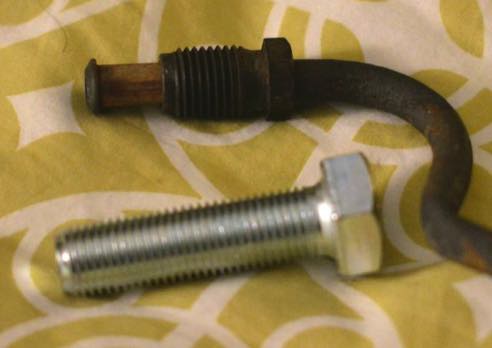
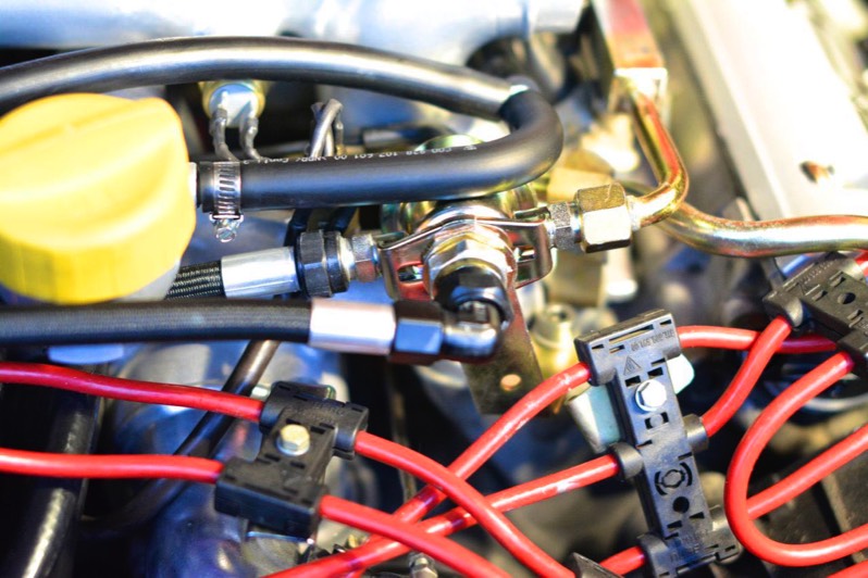
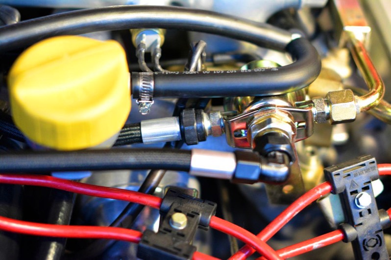
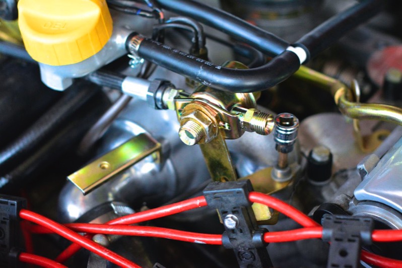
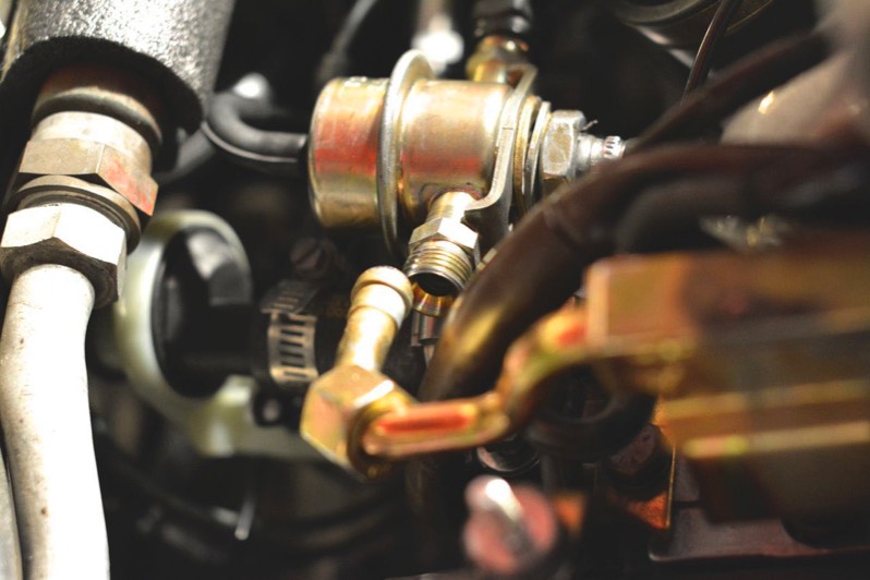
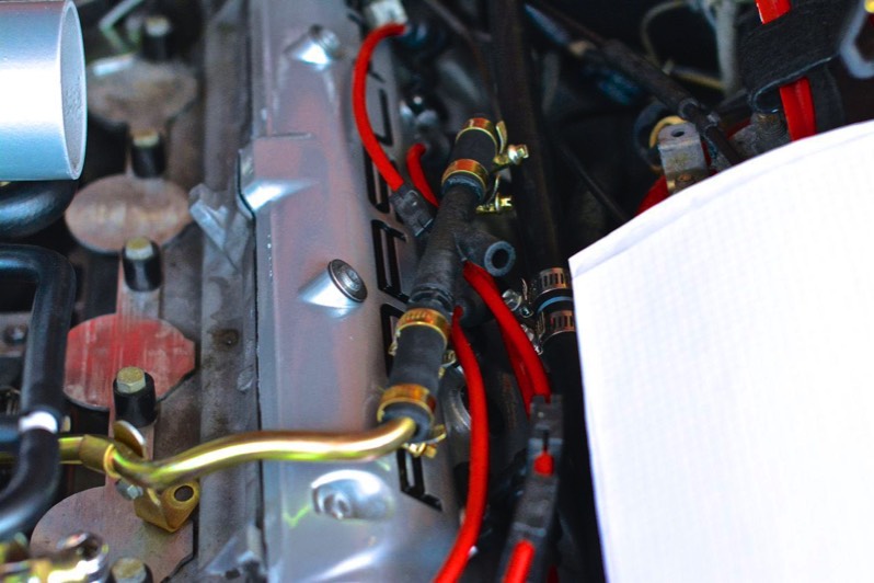
3) Optimol Paste TA. I bought this from Roger Tyson at 928sRUs. It is a silver-colored anti-seize. I used this every time aluminum made contact with steel. This included the threads of bolts, and when I connected male ends of the fuel system (steel) with the female ends of Greg Brown fuel lines (aluminum.)

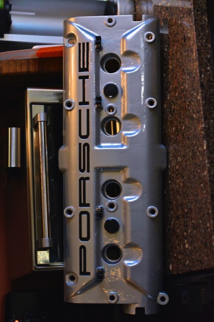
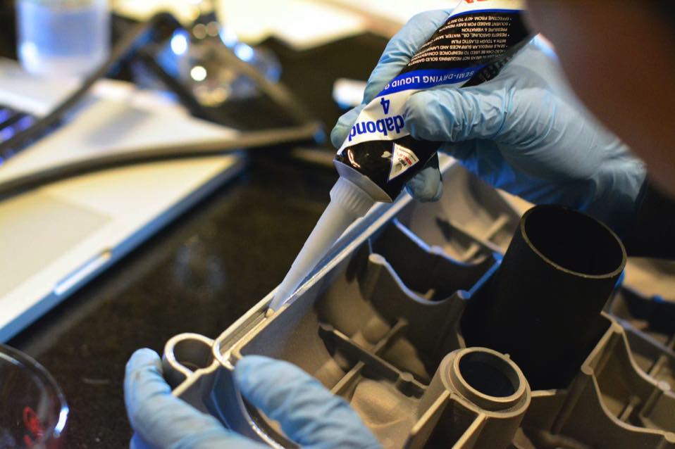
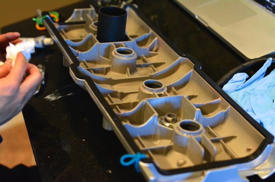
4) Hondabond 4. I believe this is also called Yamabond. It is a silicone gasket sealer that I used in the channel of the valve covers. It is rubbery when it dries. It does not come with an applicator tip- I bought a cheap tube of gasket sealer so I could use its tip with the Hondabond.

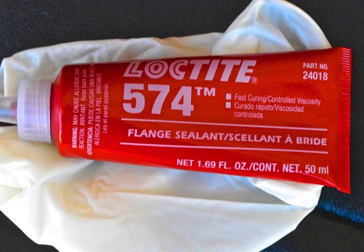
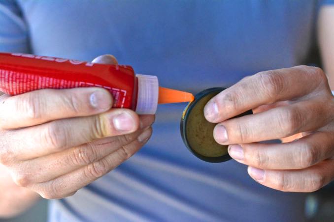
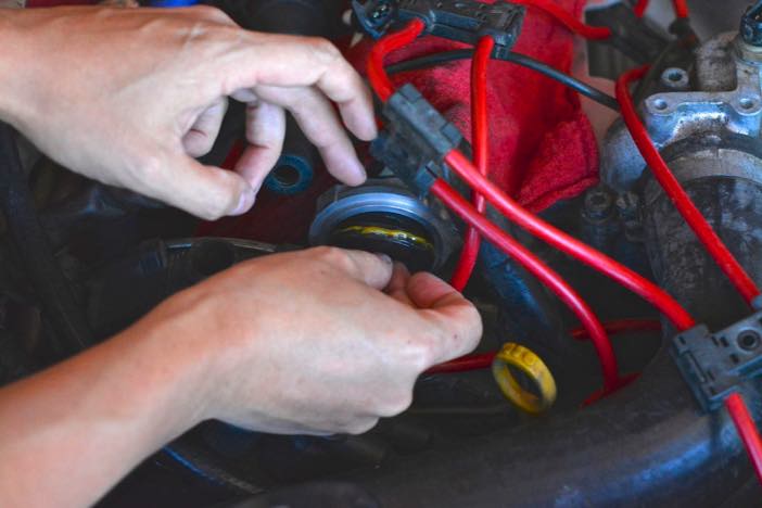
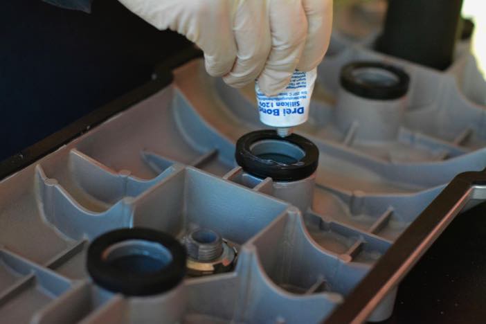
5) Loctite 574. I used this around the circumference of the camshaft end covers (aka hockey pucks.) Apparently, it needs to be stored in room temperature, and does not last long after it is opened.

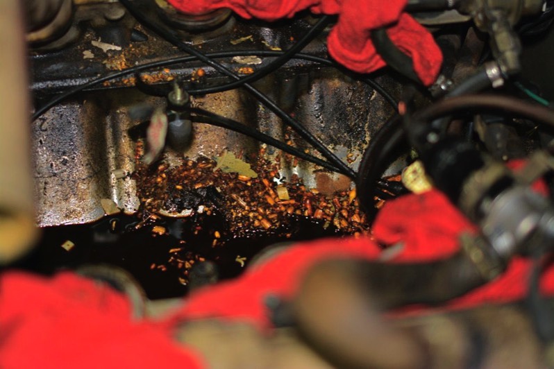
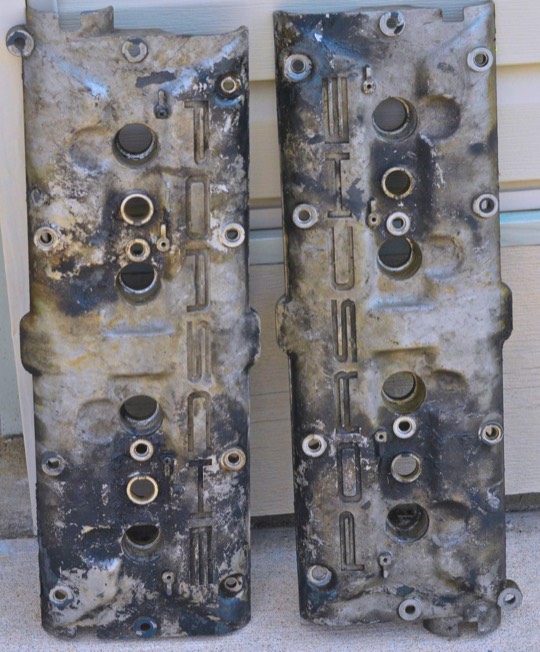
6) Evapo-Rust. I used this to remove the rust on my fuel rails, various bolts and brackets. It is great because you can reuse it (When pouring back into the container, I filtered the dirty Evapo-Rust through a coffee strainer.)

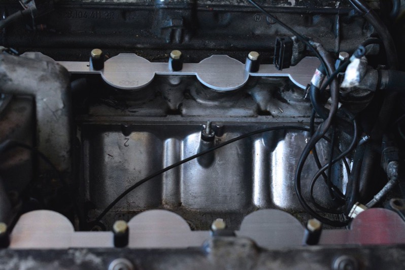
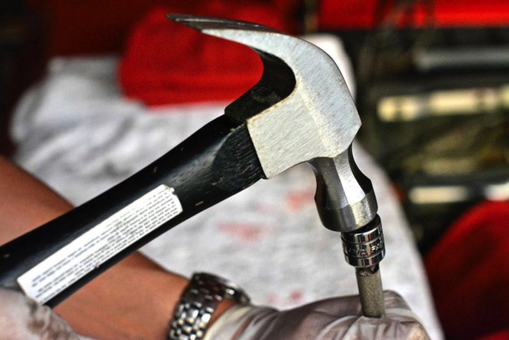
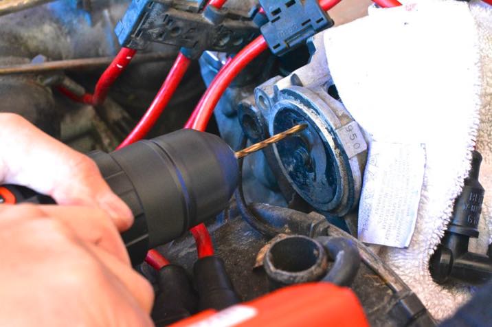
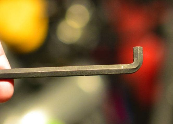
7) Stubby hex key. I needed this to tighten one of the cam cover bolts on the driver’s side that is impossible to tighten without it.

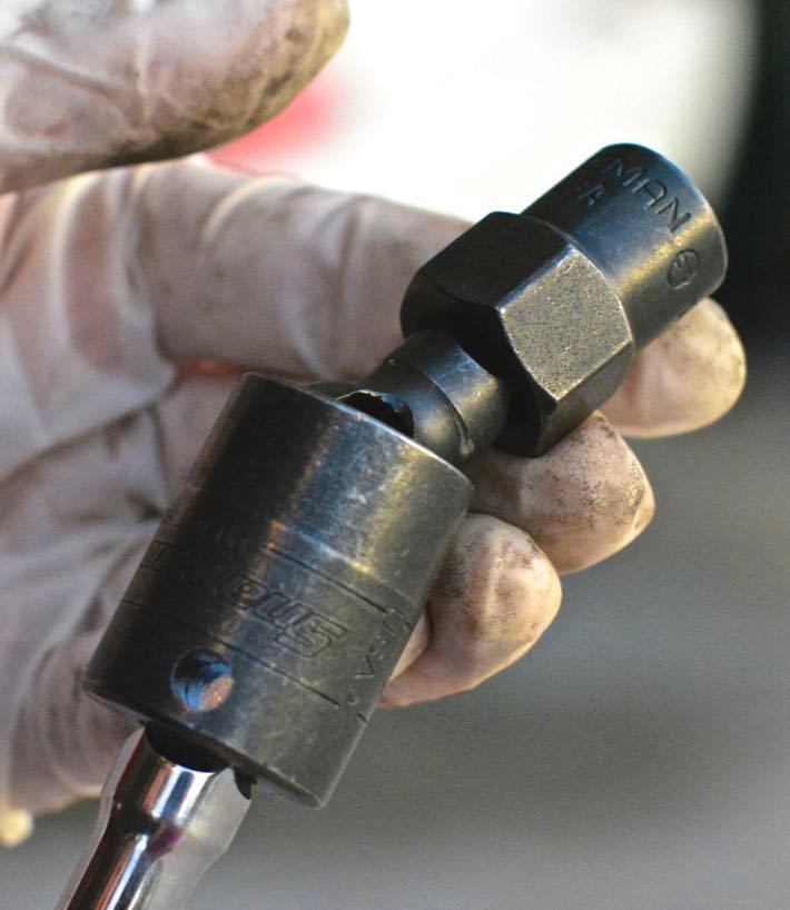
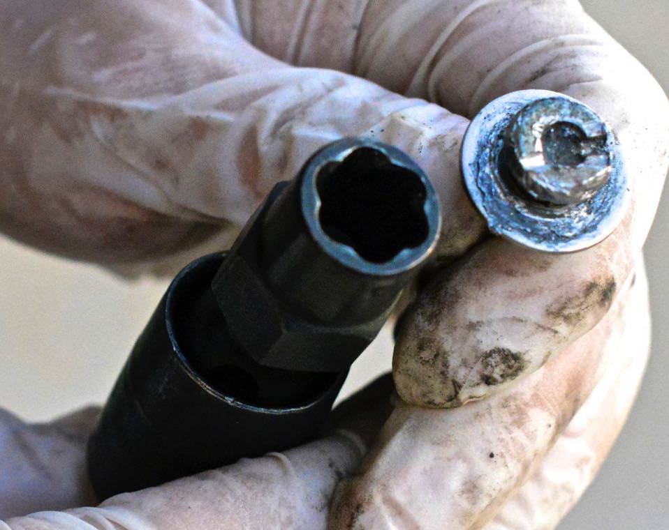
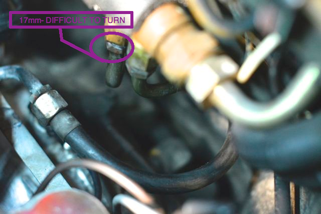
8) Crow’s feet wrenches in 17 and 19mm, to counter hold, remove (and replace) the fuel line from the fuel cooler to the fuel pressure regulator. (If you decide not to replace fuel lines, you won’t need this.)

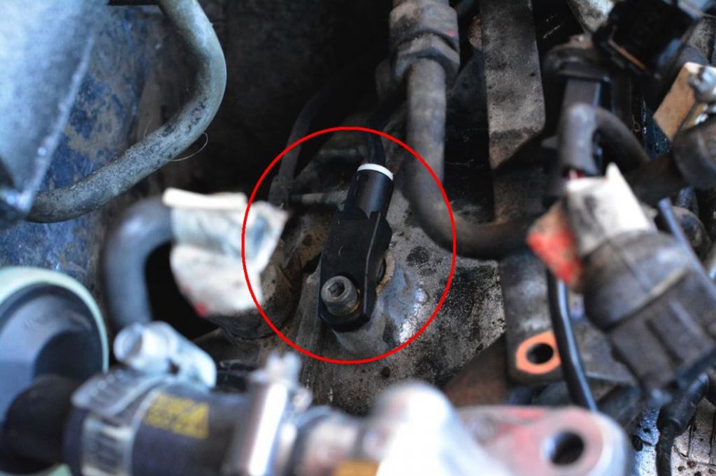
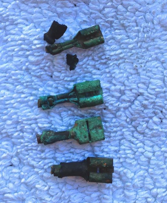
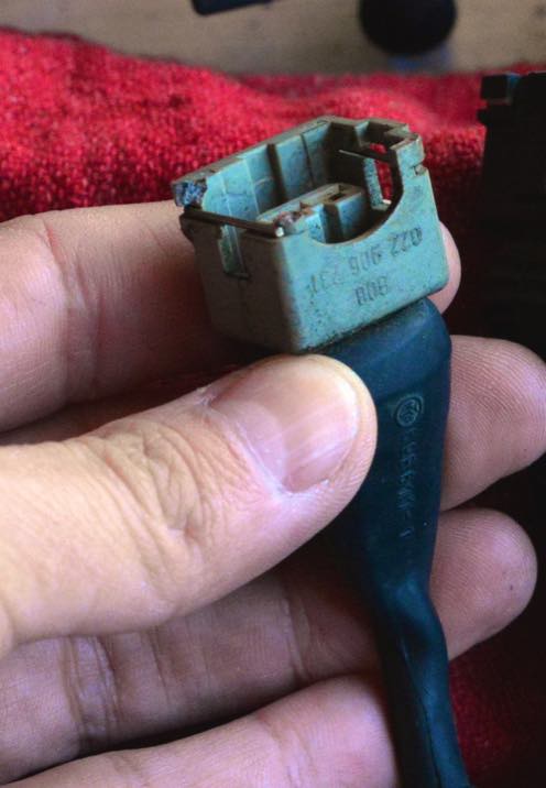
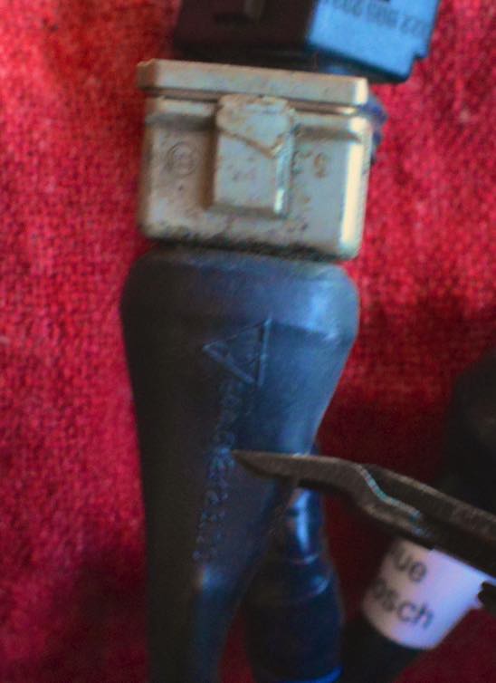
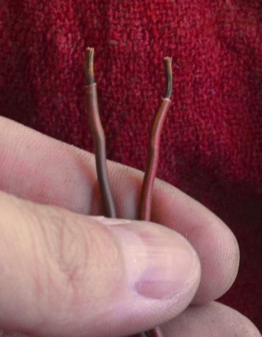
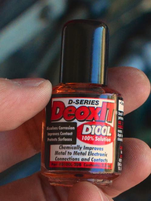
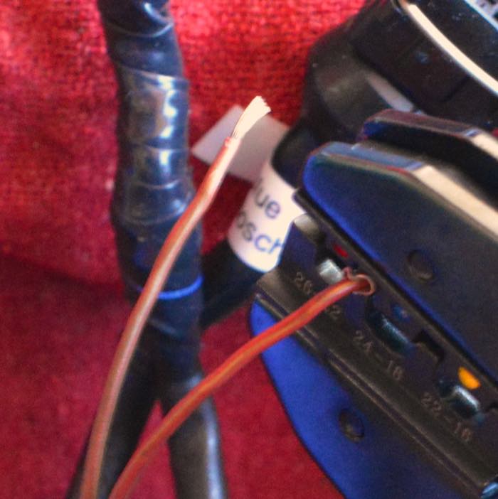
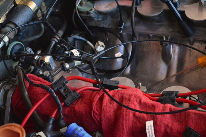
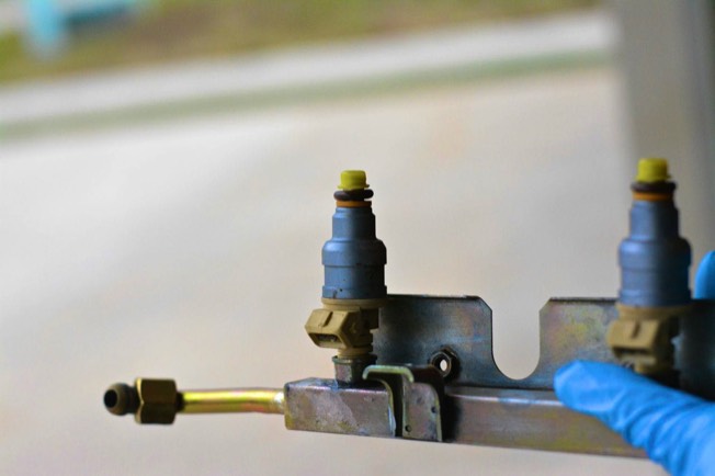
9) DeOxIT. I used this on every Bosch terminal (male and female ends.) Injector plugs, temperature sensors, things like that.

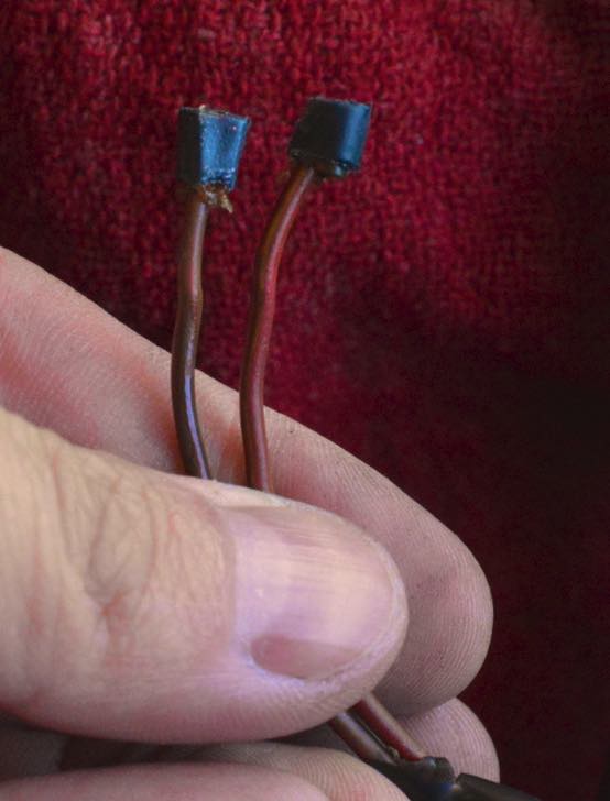
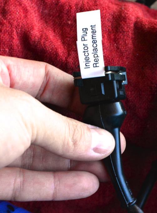
10) Butt splices. I used these when replacing broken injector plugs. Roger sells injector plug kits that include a new plug, terminals, and boot.

11) Danco Silicone Faucet Grease. I bought this to lubricate the injectors before they went into the fuel rails. According to several sources, it is Dow Corning 111, repackaged in a different container. Dow Corning 111 Dow Corning 111 is more expensive and hard to find, while the Danco product is available at Home Depot.

12) Kroil. Any time I had a nut, bolt, anything that wouldn’t turn, I applied Kroil and let it sit overnight. It really saved me with the bonded rubber buffers that were broken and difficult to remove.

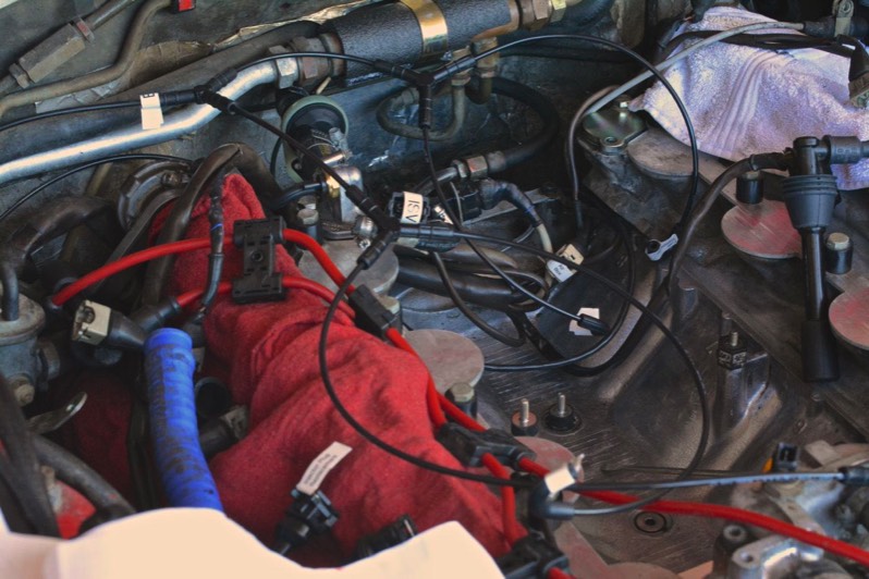
Before starting the procedure, as Mike Frye recommends, I ran the car (until it stalled) with the fuel pump relay (relay XX) disconnected, to empty the car’s system of gasoline. I also disconnected the ground strap at the rear of the car.

Remove the air filter [928 110 185 03, #4 in the diagram to the right] by unbuckling the four straps that hold the upper air cleaner part [928 110 230 06, #3 in the diagram.] (I carelessly left the left the upper air part- a plastic piece- on the fender of the car. Inevitably, it rolled off and shattered.)

Once the upper air part is removed, remove both intake air tubes (#1 in diagram) and set aside.

The air cleaner lower part [928 110 229 01, #5 in diagram] is held down by two 10 mm nuts. Remove those. The bottom of the air cleaner lower part is held to the Mass Flow Sensor (MAF) by a large hose clamp [#8 in diagram.] This clamp needs to be loosened as well.

The air cleaner lower part has a sensor with a Bosch-type connector on it [#7 in diagram.] These connectors can be infuriatingly difficult to unplug.

The two intake side plenums are each held on by five clamps (10 clamps total) that circumscribe five rubber sleeves on each side.

Loosen all ten clamps, being careful not to drop them.

Eight (four on each side) are smaller. 928 110 343 00 Two (one on each side) are bigger. 928 110 347 00

Someone who previously worked on the car folded one of the sleeves when installing the side plenums.

Gently disconnect the oil breather hose that is attached to the driver’s side intake side plenum. I used too much force, and ended up ripping the hose.

Disconnect the carbon monoxide (CO) test port [928 111 149 03] that is attached to the rear of the side plenums. Be careful because these test ports- long pipes that come up from the exhaust manifold, are often very brittle. Both of my test ports broke off in the process, and I ended up ripping both test port pipes out. I went to my local hardware store and found that an m14 bolt with a 1.5 thread pitch would seal the hole in the exhaust manifold. (I cut the bolt so that it would approximate the dimensions of the test port pipe.)

At this point, I gently wriggled each intake side plenum free, and put them aside. I compulsively started picking at the peeling paint of the driver’s side plenum, exposing the corroded magnesium underneath.

We cannot free the intake runners yet because there are a lot of things in the way. I removed the spark plug wire harness, which screws into the sides of the fuel rail. Remove both sides.

The textured hose in the picture above [928 110 652 02] is no longer available, and it had some rips in it.

Roger Tyson from 928sRUs sold me 928 110 652 01, which features the swaged end of the original part– but is much shorter. I then went to an auto parts store and found a vapor hose with the same inside diameter, cut it to the proper length, and added a metal fitting and two hose clamps to fabricate a replacement.

The next step was to disconnect the fuel hoses from the fuel rails. I did these by counter-holding with an open-faced wrench. Mike Frye warned that the counter-hold point at the front of the passenger’s side fuel rail was very narrow, so I borrowed a 17mm bicycle wrench from the local bike repair shop.

Each fuel injector needs to be disconnected. This is a gigantic pain-in-the-_ because the Bosch-style connectors are very poorly designed. There is a paper-clip-like metal wire that goes around most of the perimeter of the clip, holding it in place. It needs to be pried loose to disconnect the clip. The way I ended up doing it was using a very very sharp micro-screwdriver to wedge between the clip and the connector, while at the same time having a magnet nearby to pick up the clip just in case it went flying off. I ended up breaking the connector for cylinder 8, despite being very gentle.

At this point, I started labeling everything, because everything needs to be disconnected, but reconnected (correctly) later. I strongly advise you to take lots of photos and label everything.

The diagnostic port (circled in red below) and all of the associated wiring needs to come out. They are 10mm nuts. The diagnostic port on my car was lacking its plastic cover. The port itself is made of rubber and can be pushed through its bracket. Again, label everything.

The fuel rails are held in by 10mm bolts. Once the bolts are removed, the fuel rails are supposed to wriggle out. Mine didn’t. I had to climb on top of the engine and pull as hard as I could to get them out. The injectors were still stuck in the engine when I was through.

The intake runners are held down to the engine block by 13mm bolts. Two of my runners had stripped threads (the runners are made of magnesium, not steel, to save weight) and came out almost too easily. After removing a runner, I made sure to temporarily stuff a rag into the intake port.

The intake runners are probably surrounded by a lot of junk- dirt, acorns, grass, mouse droppings. I highly recommend buying 928 Specialists’ Intake Port Covers. They will keep objects from entering the cylinders.

At this point, it was time to remove the throttle body and air guide (which, at this point, are bolted together.) The air guide is a U-shaped thing sitting in the middle of the “valley” of the engine that connects the throttle body to the MAF. There are many hoses and vacuum lines that connect to the throttle body. I labeled each of them, which made reassembly much easier.

The air guide is supposed to be connected to the engine block by three “bonded rubber buffers.” A bonded rubber buffer is a ‘sandwich’ – the two threaded ends are the ‘bread’ and the rubber cylinder in the middle is the ‘meat.’ All three of mine were broken, which meant that the air guide simply lifted out of the engine.

Once the air guide/throttle body was out, and various wires and vacuum lines were cleared away, I was greeted by this.

It was a combination of old oil, seeds, and rat hair. I scooped it out with a plastic cup from a baseball game.

After many hours with paper towels, Simple Green, a spray bottle of distilled water, and a wire brush, the valley started becoming clean.

The throttle body and air guide were also covered in oil and unidentified organic material. After removing the throttle position sensor, I dunked the entire thing into an ultrasonic cleaner filled with Simple Green diluted 1 part to 2 parts water.

I took pictures-many pictures- of the throttle body, specifically the throttle position sensor [944 606 113 01], so that I could install its replacement in exactly the same position. It is supposed to click at the slightest rotation.

The original screws were secured by some kind of thread lock- I used blue thread lock when reinstalling.

As I mentioned before, the bonded rubber buffers in my engine compartment were broken. There was no rubber left.

To remove them, I was advised to cut a slot into the top of the buffer with a dremel tool (effectively creating a slotted screwed.) This technique worked very well.

Going through the engine compartment (and without the intake side-plenums and runners obstructing the view) it was very easy to see other items that needed to be replaced. The ‘thermo-switch” [928 110 128 01] had a broken vacuum terminal, and since I was replacing that, might as well change the short hose to the heater valve [928 574 567 03], which is a wear item.

I also changed the check valve (to the brake booster) 928 355 660 03

A New Idle Speed Adjuster (a.k.a. Idle Stabilizer Valve) 928 606 161 00 and Connecting Hose 928 110 174 08

The valve covers employ 24 allen head bolts- 12 for each cylinder bank. Apparently they originally came with two-piece bolts from the factory, but a previous owner changed the bolts on my car to the newer one-piece style, used in 1987 and newer cars.

On each cylinder bank there are 9 long bolts and 3 short bolts. They are arranged in this order:

S L L S L L L L S L L L

My parts supplier, Roger Tyson of 928sRUs, sent me spacer washers, thrust washers and thrust rings that are compatible with the newer style bolts. Make sure you have the correct washers for your given bolts.

Removing the valve covers was tedious because some of the bolts are very difficult to reach. Also, the allen head bolts are very easy to strip. In fact, I did strip a bolt, and it was tricky to get it out.

First, a bolt extractor from Sears.

I attached it to a universal joint from Snap-On, and attached a ratchet extension to the universal joint.

With the help of a hammer, I was able to get a good “grip” on the stripped allen head bolt. It came out easily.

The valve covers have spark plug wire holders that need to be removed with a Phillips screwdriver, and special slotted nuts that need to be removed before sending to the powdercoater.

SnapOn sells an “antenna nut socket set” that works very well for this purpose.

While I was already “in there” I changed the ‘pulse sender,’ otherwise known as the Crank Position Sensor [944 606 115 00.] It is at the very rear of the engine.

I also removed the oil filler neck and the water bridge.

Both valve covers, oil filler neck, all intake runners, and the cross brace were sent to be powder coated by Ben Genovese at Legend Garage. He specializes in the 928, and his work is impeccable. All of the pieces came back in spectacular shape. I washed them thoroughly in a bathtub with soap and a soft brush until there was no more blast media remaining in the bottom of the tub.

Quite a difference!

I let the water bridge sit in the ultrasonic machine for a few hours, and then polished the elbow with a little metal polish.

The water bridge is illustrated in #25 below. (It is called regulator housing in PET.) Sometimes it is called coolant crossover.

928 606 201 01 is the remote temperature sender (#36.) Because it (and its wires) were encrusted in green corrosion, I changed the sender. I also cut back enough wire to expose bright copper, and then crimped on new spade connectors.

928 606 125 01 is the famous “Temp II” sensor (#56.) I changed that as well.

Then, there are three round gaskets for the water bridge.

999 701 627 40 (#31) goes between the water bridge and the engine block. 928 106 163 00 (#33) goes the water bridge and mates with the thermostat (#27.) 999 701 632 40 (#28) fits between the thermostat and the elbow (#29, called cover for regulator housing in PET.)

All three were changed, and the thermostat was changed as well.

Of the three gaskets, #33 above is by far the most difficult to remove. I was instructed to pinch it with a pair of pliers- destroying in the process.

The red oddly-shaped gaskets are part number 928 106 227 00. As per Greg Brown of Precision Motorwerks’ instructions, I replaced the red gaskets:

And then applied some Drei Bond 1209 to both sides of the paper gasket and put a paper gasket on top of each of the two red gaskets.

Before Installing the ‘elbow’ make sure that the thermostat is oriented correctly.

Before replacing all of the gaskets (or O-rings) around the water bridge, I rubbed each gasket with Dow-Corning 111, which keeps the rubber soft. Then, I reinstalled the water bridge.

I changed a couple of leaking cam end seals. There are two styles. The factory used a one-piece cam end seal, which is easy to remove- just unbolt.

A previous owner replaced one of the original cam end seals with a new two-piece version. The two-piece version is more difficult to remove. I had to drill a hole to be able to insert a curved pick and pull out the cam end seal.

Installing new cam end seals is easy. After cleaning the area with Brakleen and a soft rag, I applied a thin bead of Loctite 574 to the perimeter of the new cam end seal, and then gently pressed into place.

Now, we’re getting somewhere.

Reinstalling the newly-powdercoated oil filler neck is easy.

Now, time to install the valve covers. Make sure you have everything prepared: valve covers, gaskets, Drei Bond 1209, Hondabond 4, bolts, washers, etc before you start this.

I reattached the slotted nuts (that held in the breather hose elbows) and the spark plug holders before starting this procedure.

I bought Hondabond (also called Yamabond) 4 online, but it is available at motorcycle shops as well. Since it did not come with its own applicator tip, I bought a cheap bottle of sealant and used its tip. I started slowly in one corner of the valve cover and applied a thin bead of Hondabond.

After finishing this step, I installed the valve cover gasket and held the gasket to the valve cover with my wife’s hair elastics. The exposed surface of the valve cover gasket I installed dry.

For the 8 spark plug gaskets [928 104 443 08], I applied a thin film of Drei Bond 1209 to each side of the gasket.

Many on Rennlist advise putting a dab of Hondabond in the four corners of each head (8 corners) to provide additional protection. I did this.

Then, I gently maneuvered the valve cover in place. This is not easy because there are a lot of things in the way. The hair elastics were very helpful in keeping the valve cover gasket in place.

Then, I torqued each bolt to 84 inch-pounds (7 foot-pounds.)

There were a couple of bolts that my torque wrench could not reach, so I did my very best to approximate 84 inch pounds using an allen wrench. The wrench that did the trick was a stubby allen wrench, shown to the right.

When undergoing an intake refresh, it is a very good idea to replace the coolant reservoir. It is known to be a tedious job, as it is held in by three bolts, one of which is hidden from access.

My coolant reservoir came out easily by virtue of the fact that none of the three bolts that are supposed to hold the reservoir in were attached.

The old coolant reservoir was cracked, and a rodent apparently used it as a restroom.

Several of the Bosch-style connectors were fraying. Time to change.

The connector to the cylinder 8 solenoid was broken.

Cut the connector off from the wire using wire cutters.

After the cut.

After stripping the insulation.

Now was a good time to slip on the boot that came with the terminal kit.

DeoxIT is an amazing product that clears the corrosion out of electrical contacts. I bought it online.

I used an open-barrel crimper to crimp the terminals onto the bare wire.

There are many excellent write-ups on proper crimping technique on the internet. The key for me was to find the correct die- one that fits snugly with the item to be crimped. Otherwise, as I learned from experience, the crimping tool will merely crush, rather than crimp.

Slide on the boot, and done.

I did several terminals. The Bosch connector that engages the MAF has many leads, so I was careful to keep them in the correct order and orientation.

I received new teflon fuel lines from Greg Brown. They came with instructions, and are easy to install. They are unique in that they have a lifetime guarantee. Greg Brown is the world’s foremost 928 mechanic, and I trust his products implicitly.

The fuel line from the fuel cooler was difficult to turn. I ended up using 17mm and 19 crow’s foot wrenches- one to turn, one to counter hold.

I decided to change all of the vacuum lines under the hood. They seemed fine, but hopefully the new lines will last another 27 years!

I kept the lines straight by using the vacuum line kit from 928sRUs. It is an ingenious kit that avoids the use of the 7-way splitter, which is exorbitantly expensive. I was careful to label every junction and end, so that I knew where it would go. Once you ‘install’ this kit, you will find that there are vacuum lines everywhere. I routed the lines in the most logical way I could think of- I am sure that others would have done a much better job.

Time to bolt the Throttle Body, Air Guide, and MAF (Mass Air Flow meter) together, and reinstall. This is what mine looked like, although Porken (on Rennlist) had a couple of comments.

1) The ridge down the MAF lines up with a nub cast on the housing. 2) MAF hose clamps should to be flipped over (face forward, passenger side.) 3) The red vacuum cap should be on the port next to it for California, only.

A good view of the new Idle Stabilizer Valve. I recommend that you make all of the hose clamps very tight (but not so tight as to cut the hose.) I didn’t, and had to go in after reassembly to eliminate intake leaks.

Quick note: For those of you who are using Porsche’s PET Parts Catalog as a guide, note that the MAF is incorrectly oriented in PET- it is upside-down.

Note the bonded rubber buffer that connect the Idle Stabilizer Valve to the Air Guide via two brackets.

The Air Guide sits in the valley of the engine block on three bonded rubber buffers. The bonded rubber buffer on the passenger side is longer than the other two by necessity. When installed, it should look something like this.

Take this moment to reattach the throttle linkage to the throttle body, otherwise it will be difficult later on.

Time to install the intake runners. I torqued each 13mm bolt to 15 ft-lbs, and coated each bolt with a small amount of Optimol TA anti-seize. First, the “T” that connects to the Throttle Body. I ended up rotating the hose clamps 135 degrees clockwise, so that I would be able to access the hose clamps from the rear when all of the runners were in place. Be sure that all of the clamps are tight! This is also a good time to connect the breather hoses to the “T.”

I sent the set of eight injectors to WitchHunter to be cleaned. Upon return, I took Mike Frye’s advice and connected each injector to a 9V power battery to make sure that the solenoid clicked. At this point, I inserted each injector into their corresponding spot on the fuel rail. I coated each O-ring with a small amount of Dow-Corning 111, which keeps them pliable.

Time to seat the fuel rail without damaging anything. Bolting down the fuel rail was tricky for me, because some of my intake runners (which are made of low-grade magnesium casting) had stripped thread holes. I did the best I could.

Then, I installed the remainder of Greg Brown’s fuel lines, and reattached everything that I disconnected in disassembly. (This is where labeling everything was handy.)

I also replaced both Fuel Pressure Dampers and the Fuel Pressure Regulator.

When I put the fuel rails in, to my chagrin, the fuel rail did not line up- at all- with the fuel pressure regulator.

I loosened everything and tried again. I don’t think there is any secret, I just jiggled things until the “ball” from the fuel rail mated with the “cup” of the fuel pressure regulator. Before screwing them together, I applied a thin coat of Drei Bond 1209 to the “ball” part of the fuel rail, to prevent leaking.

Then, I tested the integrity of the fuel system. I pressurized the fuel lines/rails by removing relay IV and cranking the starter.

Below, I reassembled the Diagnostic Test Port

Changed the spark plug wires

(The old ones were crispy- probably original.)

The plumbing associated with the brake booster:

… And the plumbing associated with the oil breather system.

After testing the fuel system, I put the intake side plenums on. It looks easier than it is, because it is kind of a pain to get the rubber gaskets around the tubular openings for the side plenums. What I ended up following was this procedure:

1) Put two hose clamps on runner, loose. 2) Put gasket on intake runner, but not all the way- keep it loose. 3) Put a bit of some lubricant (I used 303 Aerospace Protectant.) 4) Repeat for all five gaskets (on each side.) 5) Push side plenum into gaskets, being careful that the gaskets don’t fold. 6) Align two hose clamps on each gasket, making sure that the hose clamps lie in the “groove” that each gasket provides. 7) Tighten carefully.

Before starting for real, I restored relay IV to its proper place, and check to make sure that everything was connected. All done.