1986.5 928S Timing Belt / Water Pump Procedure

After owning the 86.5 928S for 6 years, it was time for a timing belt and water pump change. In the process, I changed all the accessory belts, and rebuilt the clutch slave cylinder, oil pump, and tensioner.

John Kelly’s superb write-up was extremely helpful for this procedure. I carefully bagged and measured every bolt and washer, and put these measurements in my notes, so that the same parts would be returned to the same places upon reassembly.

Also, I used a paint stick to paint a small white dot on any bolt that was torqued. That way I was sure that I had not forgotten anything.

NEW PARTS

Tensioner Boot 928 105 552 08 Tensioner Clamp 999 512 564 02 Tensioner O-Ring 999 701 650 40 Tensioner Gasket 928 105 611 05 2 Tensioner Arm Bushings 928 105 613 04 Tensioner Idler Roller 928 105 571 02 Tensioner Main Roller 928 105 512 12 Laso Water Pump, new with plastic impeller 928 106 015 22L Timing Belt (Gates, non-racing) 928 105 157 50G Main Crank Gear 928 105 125 12 Oil Pump Front Seal 999 113 275 40 Oil Pump O-Ring 999 701 633 40 3 O-Rings for Oil Pump Bolts 999 701 006 40 2 Cam Shaft Seals 999 113 282 40 Main Crankshaft Seal 999 113 263 40 2 Thrust Washers 928 102 125 02 2 Cam Sprockets 928 105 530 04A (aftermarket from Roger Tyson) Oil Pump Gear 928 107 107 13

Engine Ground Strap 928 612 011 00 Power Steering Fluid Reservoir 928 347 015 05 2 Power Steering Hoses 928 347 445 06 Power Steering Belt 999 192 286 50 Air Pump Belt 999 192 160 50 Air Conditioner Compressor Belt 999 192 305 50 2 Coolant Drain Plug Seals 900 123 055 30 Clutch Slave Cylinder Rebuild Kit 928 116 901 00

Porken PK32V’r Valve Timing Tool Water Pump Bolt Set Flywheel Lock Tool 000 721 916 11 Kempf Tool

The first order of business was to disconnect the battery ground strap and get the car on jack stands. Then, came the very messy job of emptying the coolant. I was not strong enough to remove the two coolant bolts with a regular ratchet, but an extra-long ratchet did the trick.

I should have used a kiddie pool, as others have. There was coolant all over the place. At this time I drained the radiator. The drain plug on the radiator is a blue plastic screw.

After removing the fan shroud, detaching the radiator hoses, wiring harnesses, removing the power steering reservoir (which I will change later in this procedure), I started having a better view. I knew I was going to be replacing all the belts, so I cut them.

The top end of the engine looked fine, but the front end was an oily mess. With a jug of P21S Total Auto Wash, a spray bottle of water, some Brakleen and brushes, I got to work.

After several hours, the front of the engine started looking better. Most of the work in this job is in cleaning.

Pulling the driver’s side timing belt cover is relatively easy. However, the passenger side was a little more difficult because the coil was in the way. I loosened the coil to get the passenger side cover out.

I saw pretty quickly that I would need to replace both cam sprockets. Using a long ratchet and a 27mm deep socket, I cranked the engine 1.75 revolutions to 45 degrees BTDC (before top dead center), and installed the flywheel lock tool, which is mandatory for this job.

Since this was my first time changing the timing belt on the 928, I was struck by how difficult it was to turn the engine by hand. Part of the problem was that I was too lazy to remove the spark plugs (because that would require removing the side plenums on an 1985-1986 engine.)

The other thing I was not prepared for was for the ratchet to suddenly spring forward from time to time. This is due to the spring pressure from the valves. It really scared me the first time.

Here is where I made my first big mistake. Since my car has a manual transmission, I needed to remove the two bolts that hold the clutch slave cylinder in place, and move the cylinder out of the way.

Unfortunately, in the process I damaged the clutch slave cylinder. I will cover rebuilding the clutch slave cylinder later.

Anyway, with the clutch slave out of the car- and damaged- I inserted the flywheel lock tool. The crankshaft won’t rotate now.

Continuing to get to the timing belt, I removed bolts from the center timing belt cover. The long one attaches to the water pump, and it had rust. I soaked it in Evapo-Rust.

After soaking in Evapo-Rust for a half hour, it came out looking like this. (Amazing, isn’t it?)

The center cover came off…

… but I heard a ‘click.’

I broke off a piece of the bottom of the center cover.

With the flywheel locked, I was free to remove the crankshaft bolt. It came off with a long ratchet attached to a 27mm deep socket. I didn’t think I would ever get it off.

The bolt, when finally removed, came with an extremely thick “washer” with a beveled edge. The beveled edge is facing towards the bolt head, away from the thread end of the bolt.

From there, it was easy to remove the pulleys (they came of with a gently tap of a dead-blow hammer.) The vibration damper (the orange thing that has the degree marks on it) came off with a three-jaw pulley that I bought at HarborFreight. Also, one of the two thrust washers came off. I threw that into the garbage, since I bought new thrust washers.

I completely loosened the tensioner to create some slack in the timing belt. I also disconnected the spade connector from the tensioner arm.

After removing the tensioner arm shaft bolt, I was free to gently remove the timing belt counterclockwise from the upper right (the driver’s side cam sprocket.) I was greeted by two very shiny and uneven cam sprockets. I needed replacements.

Next step was to free the tensioner. I removed the air pump bolt- along with the three other bolts that hold the tensioner in place- and pulled on the tensioner to set it free. Nothing happened.

Below is a picture of a hole- where the air pump bolt used to be.

I knocked the tensioner loose with a couple of gentle taps with a dead blow hammer.

Rebuilding the tensioner was easy. First, I had to clean it.

Notice the zip-tie that the previous owner used in place of the tensioner clamp!

Tensioner, disassembled with new parts.

Tensioner Boot 928 105 552 08 (looks like a black donut.) Tensioner Clamp 999 512 564 02 (brass round thing to the left of the donut.) Tensioner O-Ring 999 701 650 40 (not pictured) Tensioner Gasket 928 105 611 05 (upper right hand corner, made of paper.)

The valve support O-ring came out very easily. As soon as I breathed on it, it cracked.

Belleville Washer Stack. This expands and contracts depending on engine temperature.

Belleville Washer Stack, inserted into tensioner.

I fitted the new tensioner boot over the plunger and restored the C-clip. I “re-bent” the C-clip because it was a little bit loose.

Some people on Rennlist used a bit of gasket sealer for the tensioner boot. I used Hondabond 4.

Then, I installed a new tensioner boot clamp, crimping it with end-cutting pliers.

More cleaning, followed by removal of the water pump. I followed the advice of the knowledgable Rennlist members and scraped the mating surface of the water pump with a razor at a 90 degree angle to the engine block. It got most of the old paper gasket out. I followed up with gentle use of 000 steel wool, and then wiped up with a rag soaked in Brakleen.

Installing the water pump.

I applied Drei Bond 1209 to both sides of the paper water pump gasket. It was a very thin coat. Then, I put the water pump onto the block. It took three tries. The first time, the wiring harness got in the way. My fiancée held that for me. The second time, the back timing belt cover got in the way. The third time, it worked.

Roger sent me two new cam sprockets (pictured below), a new oil pump gear, and other items. The new oil pump gear is made of steel as opposed to some kind of alloy, which means that the 1mm (thin) washer behind it will be deleted upon installation.

Removing the main crank gear and the oil pump gear were both extremely difficult. For the main crank gear, I had to buy a two-jaw puller from Harbor Freight. Their three-jaw puller does not work for this application.

I laughed when others mentioned that the main crank gear would “slide off.” The two-jaw was only way the main crank gear would budge. There wasn’t enough room to get the jaws behind the gears, so I gently pried the crank gear forward with a wide slot-head screwdriver wrapped in cloth. The oil pump gear also came off with the two-jaw, but I didn’t need to use a screwdriver.

Removing the rear timing belt cover is very cumbersome. There are three 10mm bolts (easy) in the front, but then two 5mm hex bolts on the side. One is easily reached with a socket extension, but the other requires you to remove the driver’s side coil so that you have enough room to use a hex key.

I pulled off the lower idler assembly. In the process, I dropped one of the circlips. I hope they’re still available. The lower idler roller was so greasy and dirty, I have doubts that it was functioning properly. It obviously hasn’t been engaged recently.

Now, time to rebuild the oil pump. I inserted two bolts into the block, which gave me leverage to slide the oil pump out from the block.

Oil pump disassembly is simple because everything just falls out.

After cleaning everything and massaging everything with a light coat of motor oil,

I brushed the threads of the three bolts with Optimol TA (anti-seize for steel-aluminum applications), and rubbed the three O-rings with Dow Corning 111 (keeps rubber happy.)

The blue O-Rings for Oil Pump Bolts are part number 999 701 006 40.

Then, I coated the oil pump gasket with a light coat of motor oil. I also coated the new rubber O-ring [999 701 633 40] that surrounds the oil pump with a light coat of STP.

The first time I pushed the new oil pump gasket in [999 113 275 40], the spring that surrounds the inner circumference of the gasket fell out, so I had to clean it off, pull the gasket out, put the spring back in, and then reinstall the gasket.

I added a “generous amount” of STP to the oil pump right before installation.

Reinstallation of the oil pump is easy, just remember the orientation of the oil pump when it came out (I took a picture) and then reorient the same way. I put the bolts in early on so that the oil pump would line up.

Pulling the crankshaft seal was very easy in the end.

I fooled around with a drill for a while, but it ended up mangling the old crankshaft seal.

What ended up working was to hold a flat-head screwdriver at a 45 degree angle to the crankshaft at around a 4:00 position, and then lightly hammer the screwdriver in. What this did was force the crankshaft seal out. There is a grooved that Porsche designed for this purpose.

I hammered the new main crankshaft seal [999 113 263 40] in by using a PVC pipe (with an appropriate diameter) and a hammer, being careful not to ever hit the radiator in the ‘backswing.’ (I did, once.)

I coated the inside diameter of the new main crank gear [928 105 125 12] with Optimol HT (anti-seize designed for steel-on-steel applications.)

I almost forgot to include the thrust washers [928 102 125 02.] They are oriented in this direction: ] G [ where G is the main crank gear, and the [ ] are the orientation of the thrust washers.

I had a brief (actually, not so brief) moment of panic. The cam sprockets- untethered by a timing belt at this point, were at their proper position. You can see the white dot that I painted to show its alignment with the indentation on the rear timing belt cover (slightly yellowish.)

When I wasn’t looking, the cam sprocket rotated a few degrees clockwise. (!)

Since my engine was set to 45 degrees BTDC, I was able to turn the cam sprocket counterclockwise a few degrees in order to restore their proper position.

I received the new (improved) aftermarket cam sprockets from Roger Tyson at 928sRUs. They looked much better than the old ones.

I installed the new cam sprocket in precisely the same orientation that the old one came off. The Porken PK32V’r cam timing tool will help refine the timing.

Now, onto refurbishing the clutch slave cylinder.

When I installed the flywheel lock tool, I pulled out the Clutch Slave Cylinder push rod (so that I could move the Clutch Slave Cylinder out of the way) and the push rod’s rubber cover ripped (as seen below.)

I ordered a Clutch Slave Cylinder repair kit from Roger. It comes with a new circlip, new rubber cover, new retaining ring, new dust cover, and new dust cap for the bleeder screw.

I disassembled the Clutch Slave Cylinder, and the parts came out very easily. I cleaned them in kerosene.

This was the “brake fluid” that dripped out of the Clutch Slave Cylinder. (The clutch and brake systems share the same hydraulic fluid.) Obviously time to bleed the brakes!

Beginning reassembly of the Clutch Slave Cylinder.

Everything is very clean. The gasket (6) that goes around the piston (5) was difficult to get onto the piston.

I lubed the gasket with grease, which allowed it to slip on.

After wetting the inside of the clutch slave cylinder with some brake fluid, everything fit.

After I re-assembled the clutch slave, there is a circlip that needs to hold the whole assembly together. The circlip was difficult to install for the first time. (It would be easy to do it again.) What I did was:

– Push half of the circlip in, say from 12:00 to 6:00. – Push 7:00 in with a screwdriver. – Repeat for 8:00, 9:00, 10:00. What happened for me was that 11:00 and 12:00 would not fit. – For 11:00 and 12:00 put a screwdriver at the base of the “tine” and lightly tap with a hammer.

Now it is time for the camshaft rubber seal replacement. It is very easy (kind of.) You have to take the timing belt off and cam sprockets off to start.

I removed the three-pronged hub 928 105 459 00. I pulled that off by wiggling it. If the Woodruff key is not cooperative, give it a light tap with a hammer.

The Woodruff key is held into the groove by friction only, so you can change the orientation of the key by tapping one side of the key or another.)

– I removed three M6x18 bolts from the front of the upper rear timing belt cover. Easy.

– I removed two 5mm allen bolts from behind the rear timing belt cover. More cumbersome. I have very thin hands, which makes it easier.

– I pulled the upper rear timing belt cover off gently. This is an excellent opportunity to clean it.

Getting the rubber seal was tricky. I drilled into it (something that always makes me very nervous), and then stuck a thin screwdriver into it and pried it out. Keep in mind that the rubber seal is rubber-coated metal.

Pushing the new cam shaft seal [999 113 282 40] is easier than pulling out the old one. However, the first couple of times I pushed the seal in, the circular spring (looks like a silver hula-hoop for a Barbie doll) was dislodged from the inner circumference of the seal. Upon my third try, it seemed to be okay- although, since I cannot see through metal, I am only 95% sure that the spring is properly in place.

I installed the tensioner. I applied, as per the Workshop Manual, Loctite 574 to the upper-right bolt on the tensioner. I applied Optimol TA to the threads of the other bolts. At this time I fed the upper left hand bleeder with oil. Some experts recommend STP, I just used regular motor oil.

I used an oil can, pushing the nozzle into the tensioner (taking out the bleeder bolts for both inlet and outlet.) It took a while. I was expecting oil to gently pour out of the outlet in 30 seconds. Instead, oil poured out of the inlet. I had to keep trying- finally, after five minutes, oil started dripping out of the outlet. Buttoned up both sides.

(Note: the inlet bleeder bolt is the upper left, the outlet the lower right.)

John Kelly’s manual states to tap in the upper idler roller [928 105 571 02] with an appropriately-sized socket and a hammer. I did, but not enough.

What did that do? Well, when I installed the tensioner arm, it was touching the upper idler roller, so when I tightened the bolt that goes into the upper idler roller boss, the upper idler roller stopped moving. Yikes.

Here is the roller [928 105 512 12] on the tensioner arm. I installed new tensioner arm bushings as well. 928 105 613 04.

I installed a Gates (non-racing) belt into the car. When installing, ensure that the lettering is legible (i.e. not upside-down.)

I “strung” it up, as John Kelly recommends, starting with the main crankshaft gear, counterclockwise (CCW) to the oil pump gear, CCW to the driver’s side cam sprocket, down under the water pump, over the upper idler roller, over the passenger’s side cam sprocket. I made sure that the power cord (for ABS and the headlights) went through the timing belt.

I installed the tensioning arm. I put a bit of Optimol HT in the little “divot” that the tensioner arm fits into.

Now that the timing belt is strung up, I highly recommend that you activate the tensioner with the tensioning bolt. Otherwise, while cranking the engine you can skip teeth. (!)

One more time: DO NOT TURN THE CRANK WITH THE BELT ON WITHOUT IT BEING TENSIONED.

I tried the PK32V’r timing tool made by PorKen. It is very easy to use. You take the two clamp rings that are included in the the kit, and with included allen bolts you bolt the clamp rings into the three-pronged hub 928 105 459 00.

The arm of the unit is the “brains” of the PK32V’r. It has tiny little holes that you put a needle through (needle also included.)

Push the needle through hole that allows your needle to reach the deepest part of the groove behind the cam gear. That will give you the “reading” of how advanced/retarded your timing is.

I also got the PKBumpStick, which allows you to rotate the cam sprocket with an included wrench.

That’s great in theory.

Here’s what happened to me:

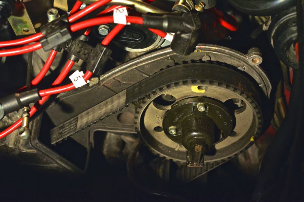
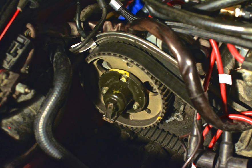
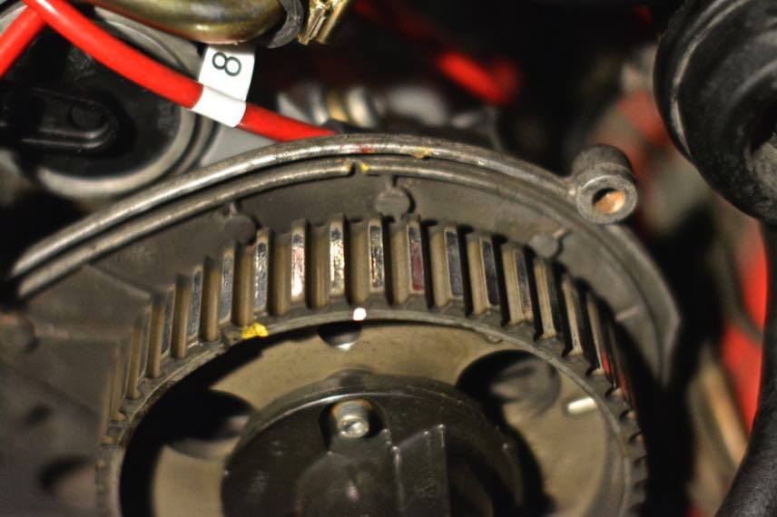
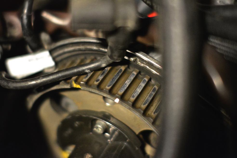
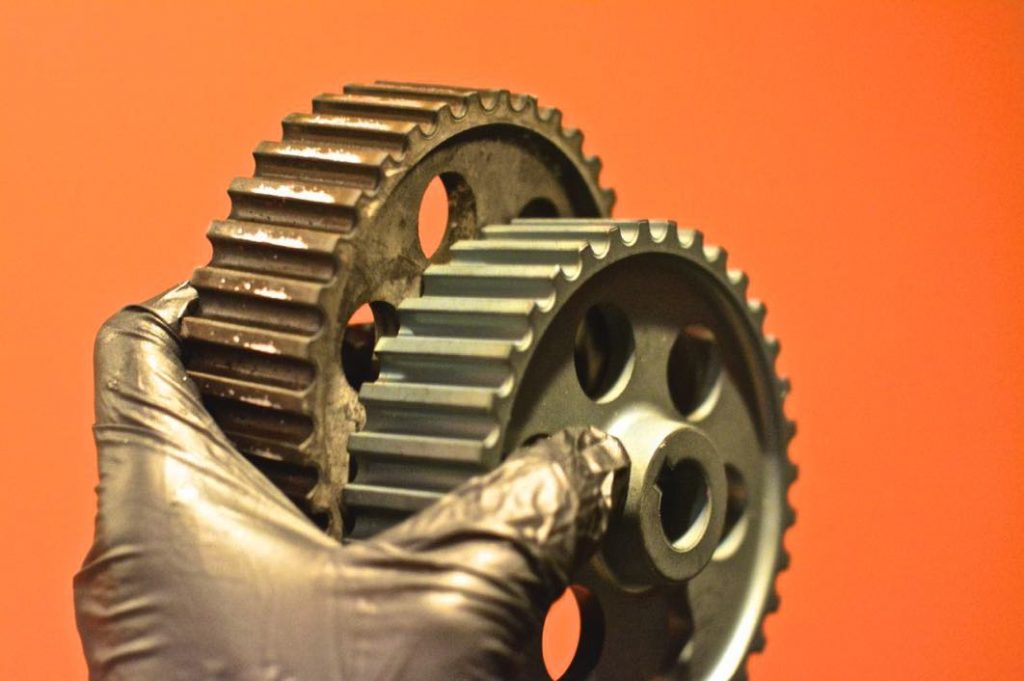
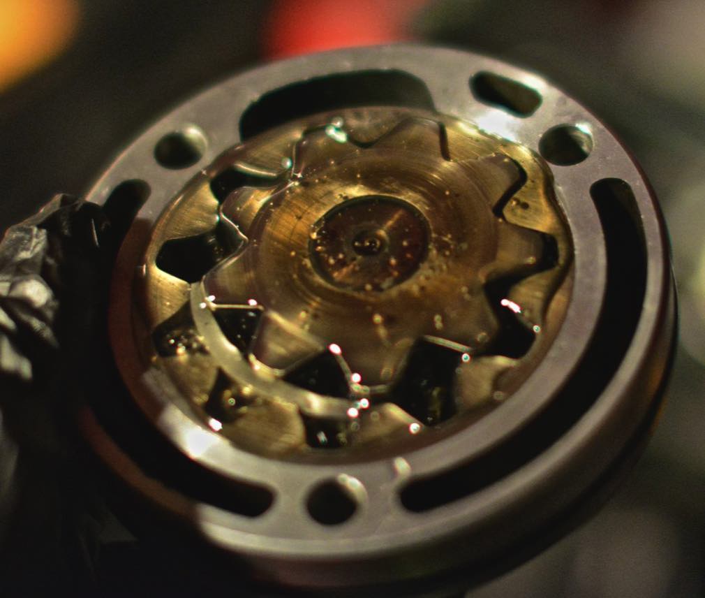
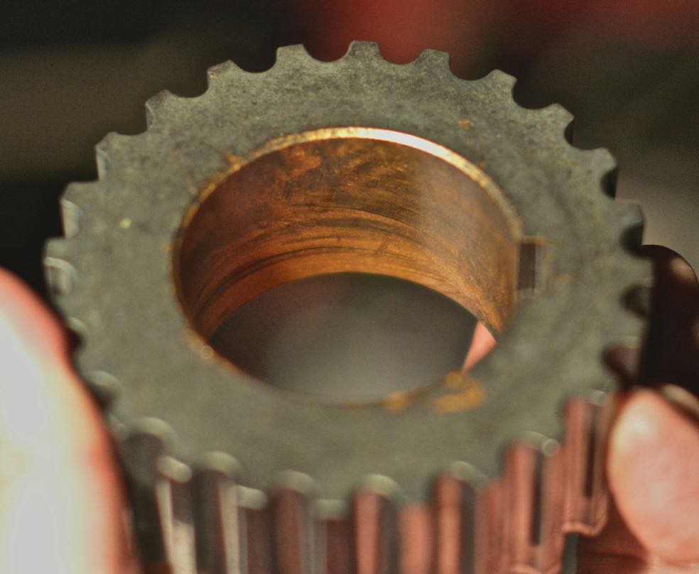
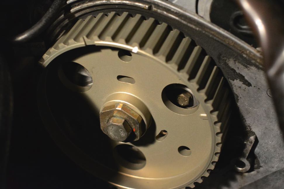
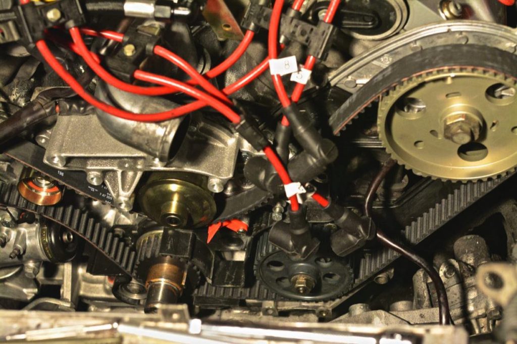
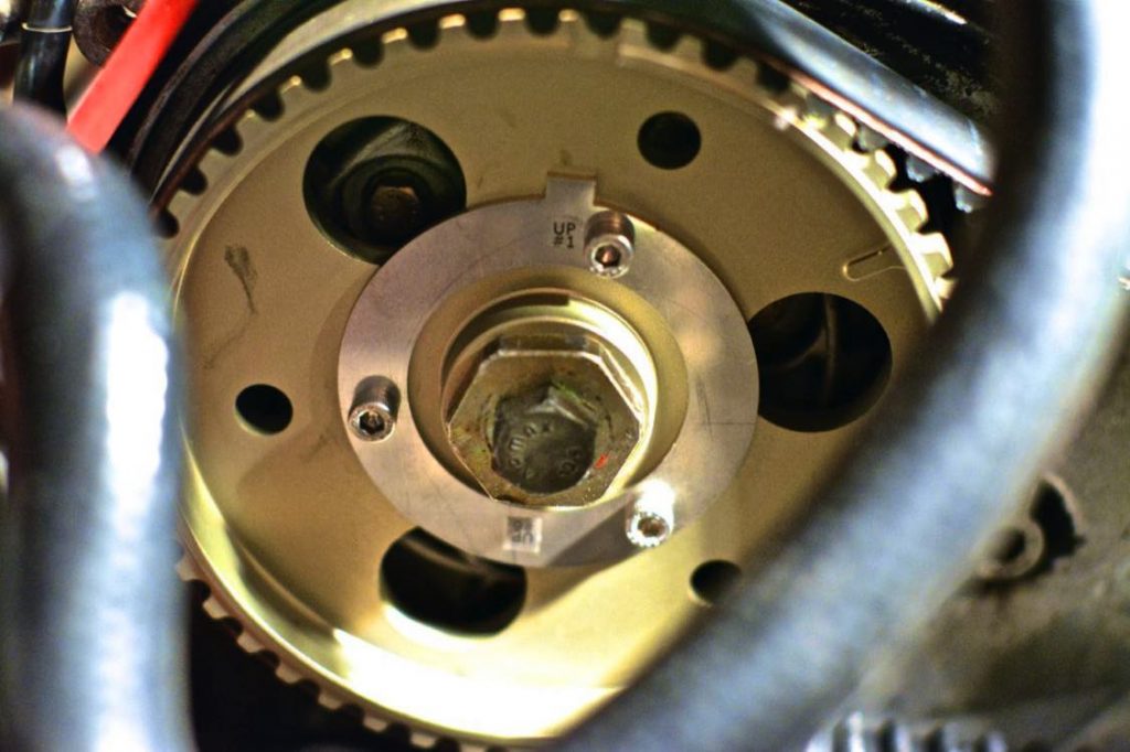
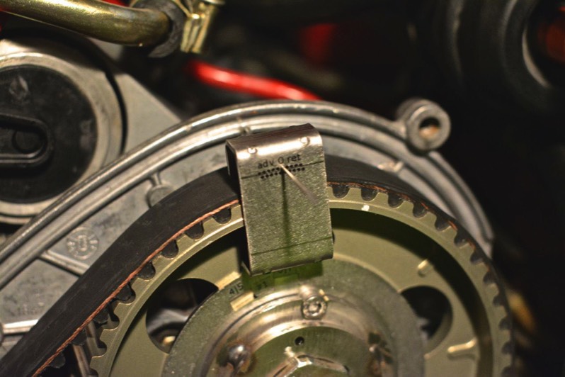
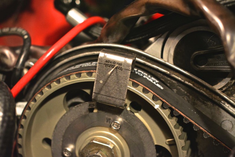
1) The little groove in the front of the cam sprocket is not an accurate descriptor of where TDC lies. When I used the PK32V’r tool on my DS (driver’s side) sprocket, I was very surprised to find out that at “TDC” (according to my cam sprocket) the cam timing was so far advanced that it was outside the range of PK32V’r tool. In other words, I was one tooth off.

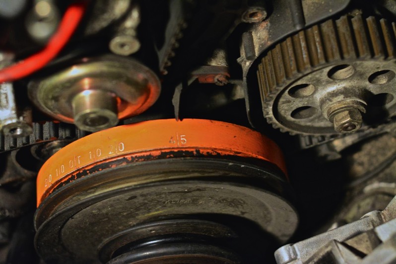
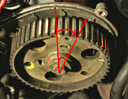
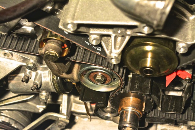
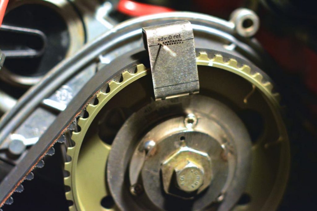
2) Using the PKBumpStick and PK32V’r, I was able to retard both the PS and DS cam sprockets. This involves setting the crank to 20 degrees BTDC, then rotating the crank until the needle in the arm of the PK32V’r resides in the deepest part of the groove. Then, you loosen the three allen bolts on the clamp rings while simultaneously holding the wrench (included with the BumpStick) in place (this is harder than it sounds.) Then, rotate the crank to TDC and tighten the allen bolts.

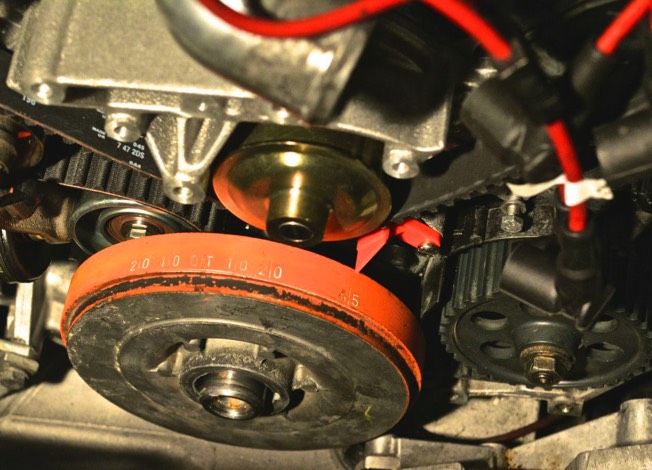
3) The procedure worked just fine- kind of. I had to do each side several times. The really crappy thing is turning the crank. It takes a great deal of effort to turn that crank two revolutions (720 degrees), especially because I did not remove the spark plugs.

The problem I had is that after turning the crank, the measurement on the PK32V’r would be slightly different each time. It is frustrating.

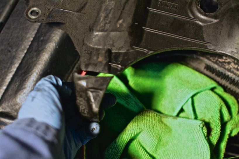
At this point, I started buttoning things up.

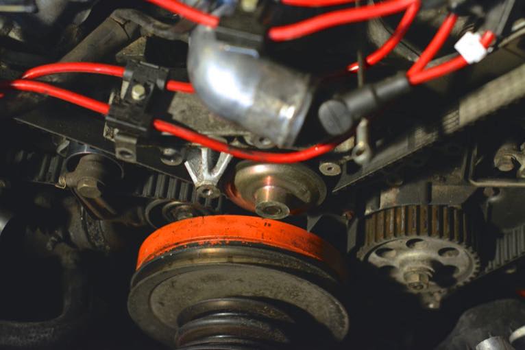
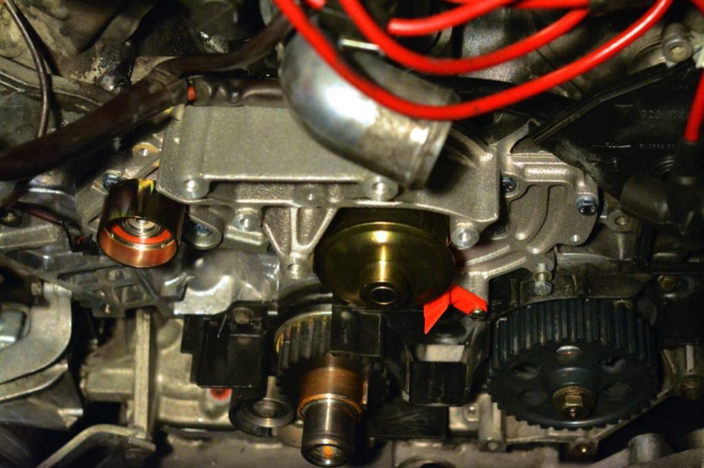
– The passenger side rotor and timing belt cover went on just fine. Five minutes- easy.

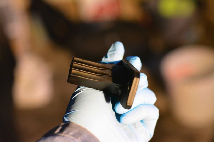
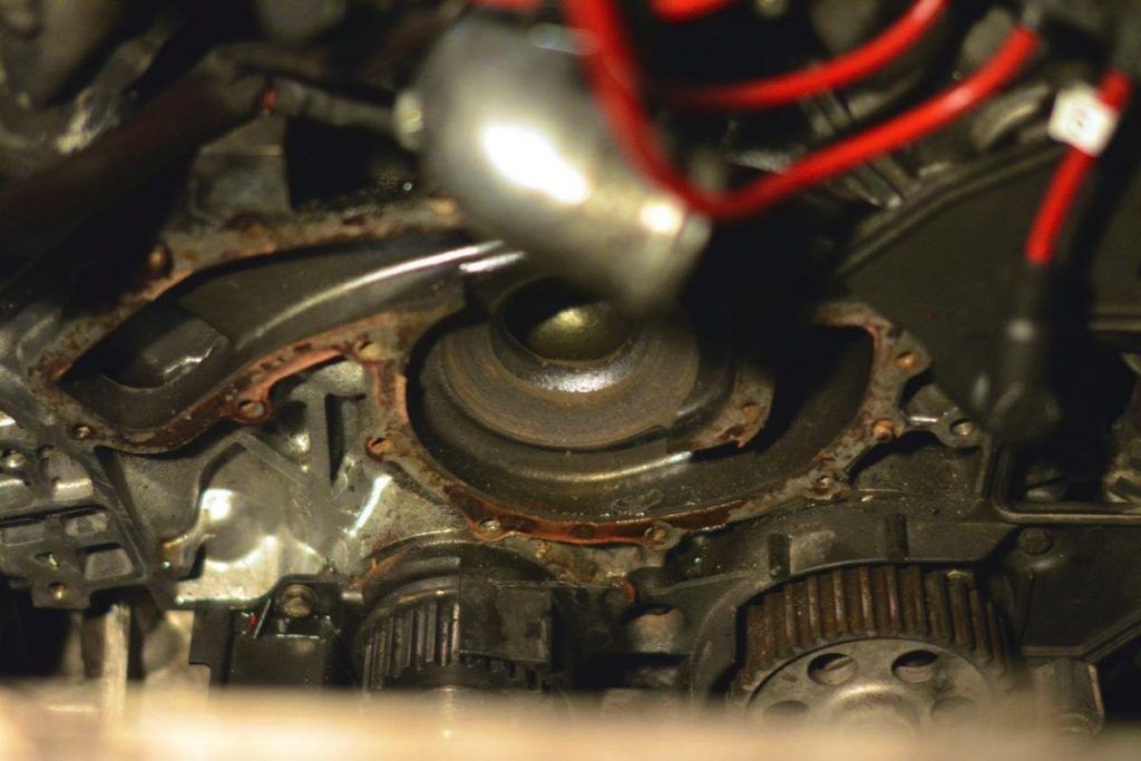
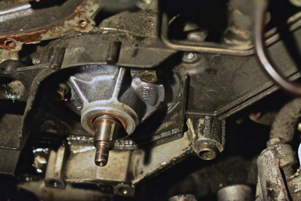
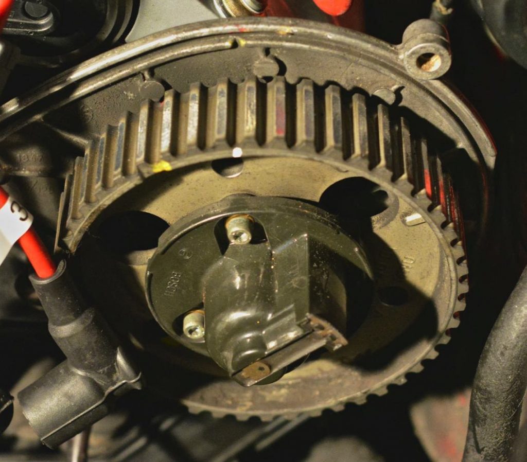
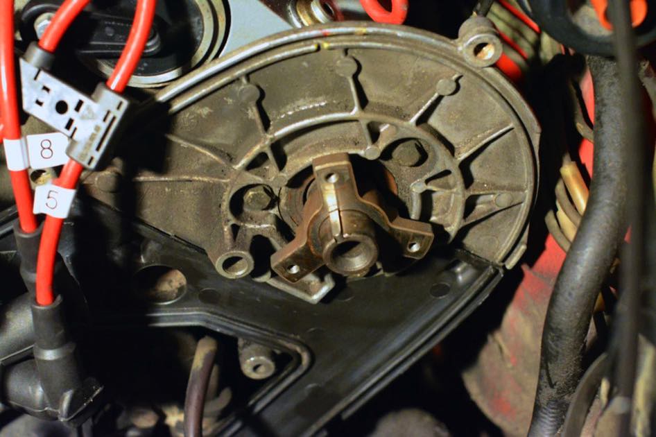
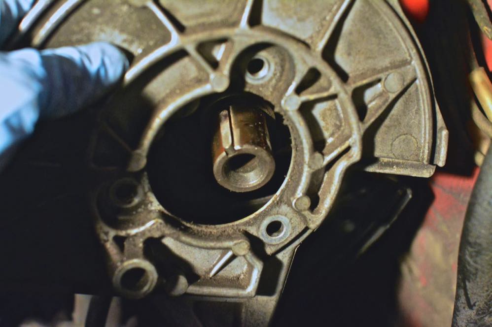
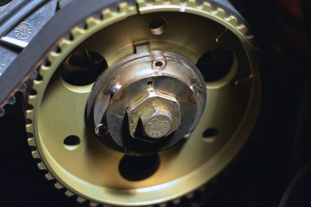
– The driver’s side rotor would not go on. The bolts could not thread onto the three-pronged hub. How could this be? I just had three allen bolts threaded into the three-pronged hub when I used the PK32V’r tool, unless… UNLESS THE SPROCKET SLIPPED WHEN I REMOVED THE PK32V’r TOOL. Five minutes turned into > 1 hour, re-timing the driver’s side cam sprocket.

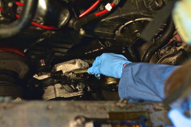
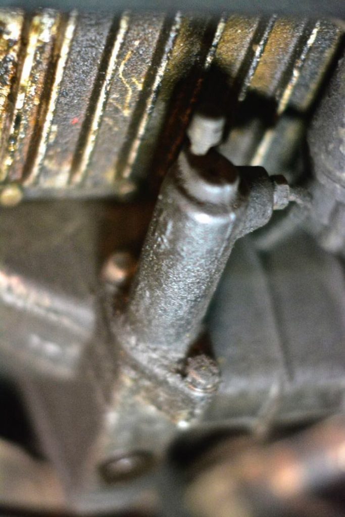
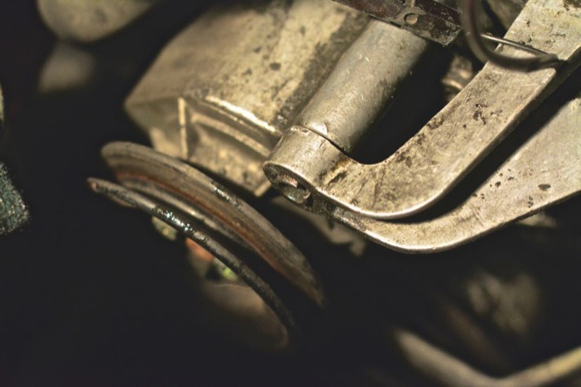
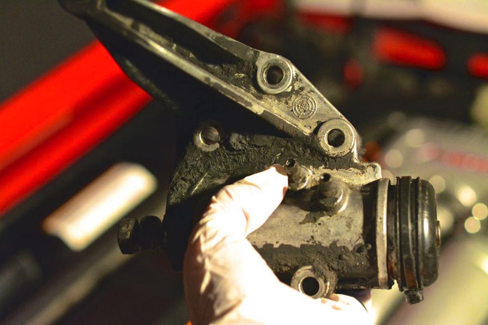
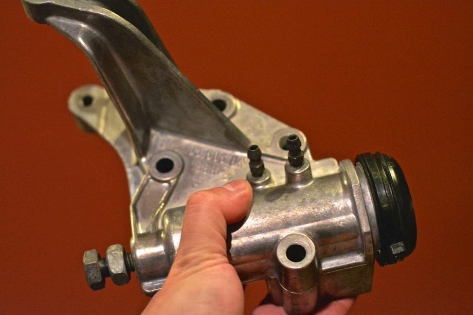
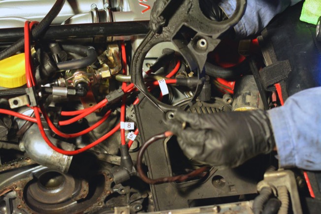
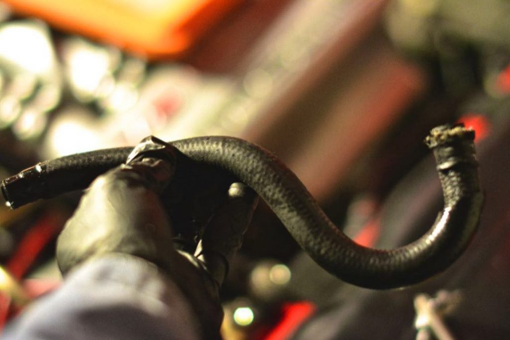
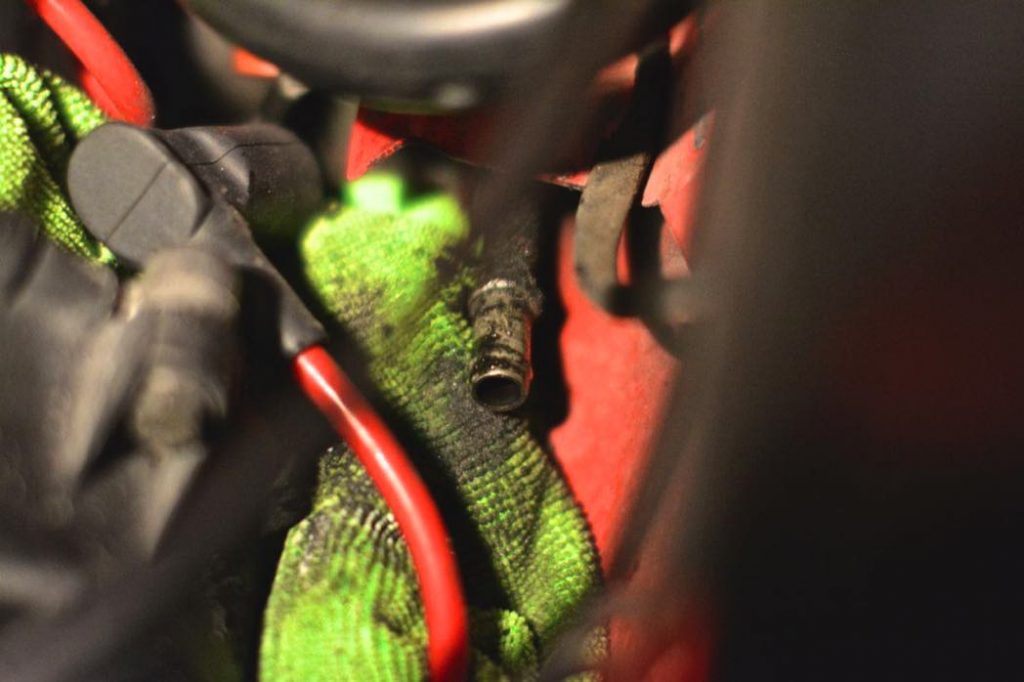
– I had to change the power steering hoses. I pulled off too many bolts, and the alternator was disconnected as well. Cleaning the power steering pump with a brush took an hour. Then, I decided to clean the ATF fluid that spilled from the banjo bolt when I disconnected it. (I had a catch pan ready but the ATF fluid traveled down my wrench.)

– I had to reinstall the alternator. There is a long M10 bolt that threads through the alternator in two places, and through the power steering pump “cassette.” I was warned that removing the alternator was very unpleasant- luckily I experienced it first hand. I finally got it on by lying down on my back and using my knees (the alternator is very heavy for someone like me.) Aligning the holes was very enjoyable, indeed. About an hour there.

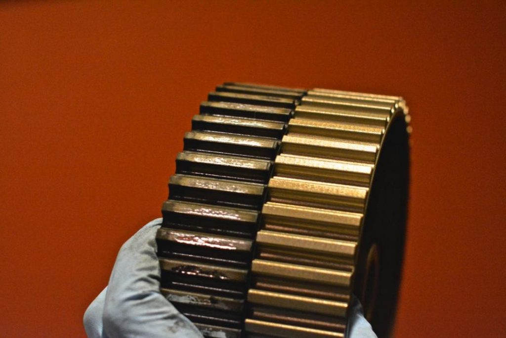
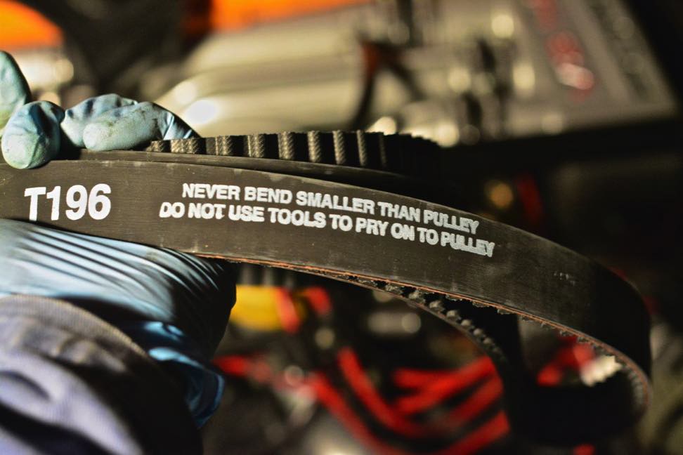
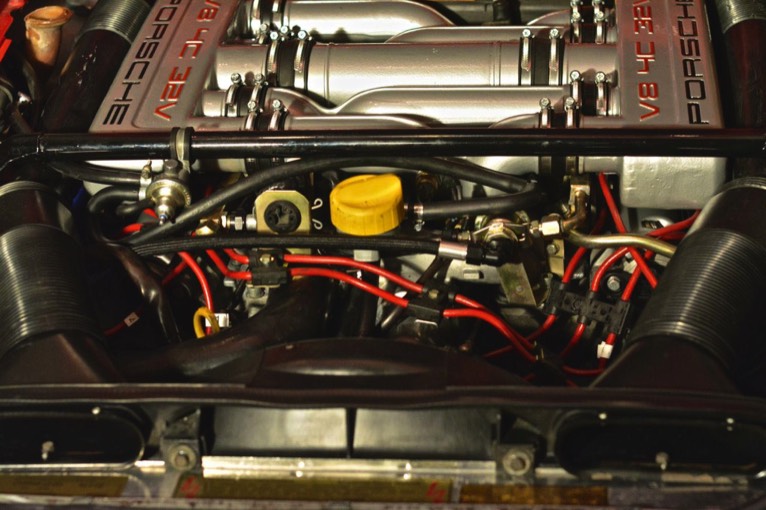
After many rotations of the crank, I set the tension of the timing belt using the Kempf tool. However, an even more accurate way to measure tension is with pitch, and it just so happens that the 928’s timing belt likes to be tuned to a slightly flat E natural.

I had a big power steering fluid leak on the driver’s side of the engine compartment, and this time I was going to fix it once-and-for-all.

First, I removed the power steering pump, and cleaned it.

Then, I removed the power steering/alternator “cassette”, and cleaned it. (It was so heavily encrusted in grease, I couldn’t make out a shape.)

Getting the alternator to go back on the alternator “cassette” was no small feat. It took me about a half hour on my back, supporting the alternator with my knees.

One of the power steering lines is very easy to change. The other is a “retrofit” job. I cut the crimped end from the factory off. I used a dremel tool, and it was very easy. (You need to remove the driver’s side coil before doing this.)

Once you get the crimped end off, you can pull off the short rubber hose that leads to the power steering reservoir. My old hose leaked.

Then I used a hose clamp to attach a new hose to the hard line.

After putting on all of the belts and applying the correct amount of tension to each, I was done.

Installed all the belts, buttoned up the car, installed new power steering lines, added power steering fluid.

Topped off the coolant. I spilled a little bit, and it hit the exhaust manifold. I was alarmed by the steam (from evaporating coolant) coming from the engine compartment.

Took the car for a drive. Everything looked ok.

The scariest part of the job is dealing with the cam sprockets. I was shocked by how the cam sprockets would lurch forward under spring pressure. It is very disconcerting, so if you’ve never done this job, don’t be surprised. If your crank is at 45 degrees before top dead center (45BDTC) you will be okay.

In the end, this was several projects in one.

New cam sprockets, installed New main crank gear, installed Rebuilt clutch slave cylinder Bled brakes and clutch slave Changed power steering hoses Changed power steering reservoir Changed power steering fluid (Dexron III) De-rusted bolts Rebuilt oil pump Changed camshaft seals (behind cam sprocket) Changed coolant

Good luck!